Golden Pose
Golden pose is the target pose that run time part should be aligned to in alignment or assembly applications, it is consisted of a set of feature locations. Golden pose is saved in train time and would be used in run time pose computation. There are three ways to train a golden pose:
Use current part's feature locations
This method use a run time part to a reference part, extract features of it and save their locations as golden pose. The advantage of it is the train time and run time features are the exactly the same feature types that the vision system doesn't need to set different vision tools for train time and run time feature finding.
Use reference feature locations
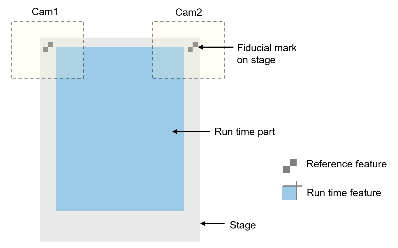
Reference feature locations can be used when golden pose needs to be fixed based on certain features on the mechanical device where the run time part rests.
In the example shown below, golden pose is trained using fiducial marks on stage. While run time features are two corners of a part. This method requires the vision system to configure two sets of vision tools, one for reference feature finding, one for run time feature finding. The benefit of this method is that the golden pose would not change even run time part type is changed, thus it maintains the consistency of mechanical operation when it comes to align or assembly.
Use camera center
Using camera center as golden pose is another way to keep golden pose fixed when part model changes without camera repositioning. Besides this, using camera center doesn't require extra vision tools for train time feature finding, which is as convenient as using current part's feature locations. However, since camera centers may not always be the ideal physical golden pose where run time part should align to, certain offsets needs to be added to camera centers so that it meets align requirement.
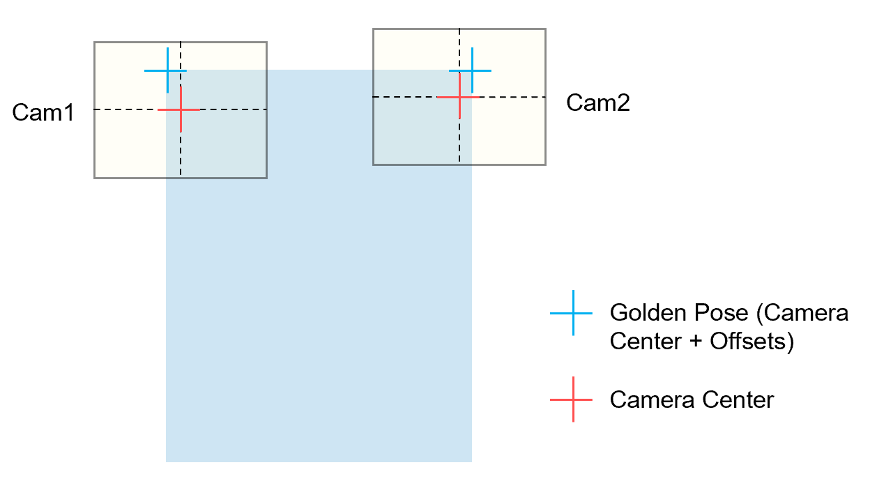
Here is an example:
The Camera1 and Camera2 are installed mechanically not along the same direction with x or y direction of the stage, and golden poses are at the upper part of field of view of cameras so that longer edge features can be captured. Thus the centers of two cameras can’t be directly used as golden poses, offsets should be added to camera centers to set as golden poses.
| Left Point | Right Point | |
|---|---|---|
| x |
Cam1_CenterX + OffsetX1 |
Cam2_CenterX + OffsetX2 |
| y | Cam1_CenterY + OffsetY1 |
Cam2_CenterY + OffsetY2 |
Camera center and offset values are all based on the same shared coordinates with run time features'(Home2D). AlignPlus provides function that allows user add offsets based on the gantry coordinates where cameras are amount to and automatically convert them to coordinates in Home2D.